

GridVolt gateway hardware
The GridVolt gateway connects the site’s energy assets to GridVolt. It is installed on site and connected to power, the local network, and the supported equipment included in the site design.
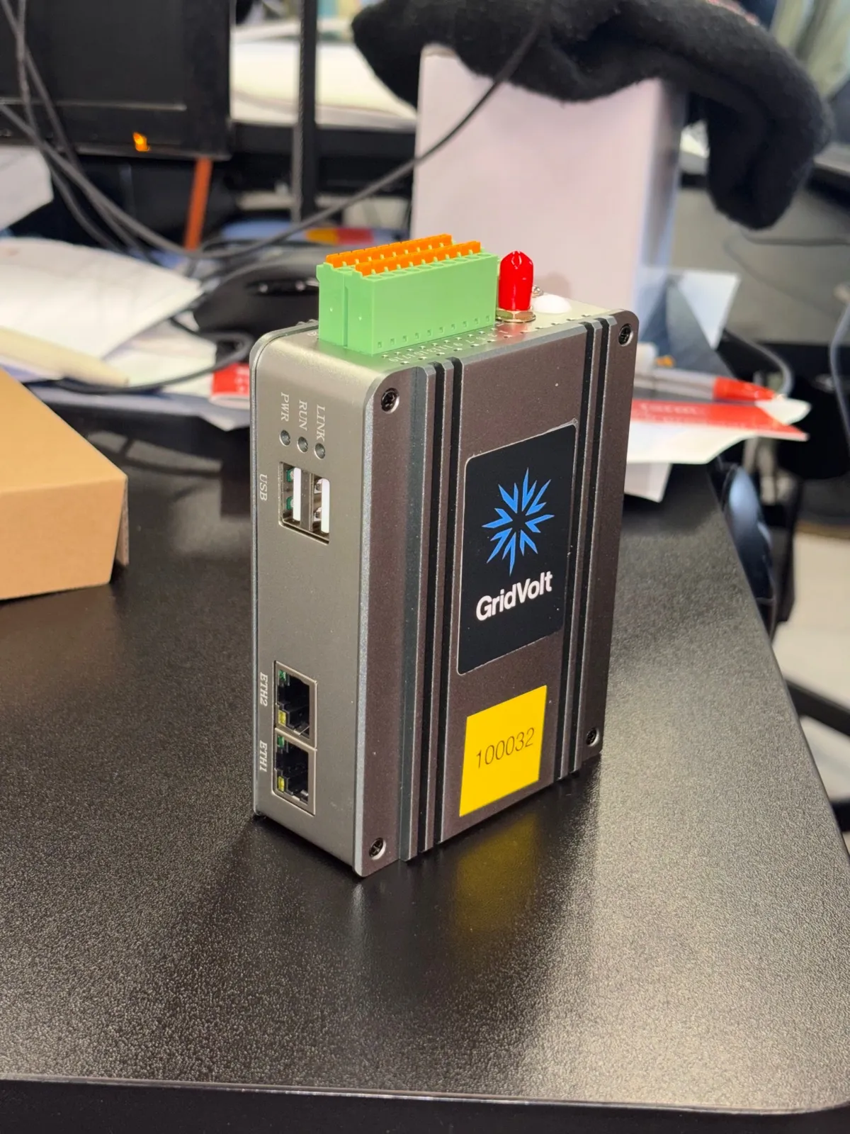
Hardware overview
Section titled “Hardware overview”| Specification | Details |
|---|---|
| Power supply | Supplied 230 V AC UK plug-in power supply with 24 V DC output |
| Mounting | DIN Rail |
| Gateway power connection | Screw terminals |
| Ethernet | 2 ports: ETH1 (LAN) and ETH2 (WAN) |
| USB | 2 ports |
| Mobile connectivity | Integrated 4G module |
| Positioning | Integrated GPS module |
| Serial interfaces | 2 configurable RS-485/RS-232 ports |
| Digital inputs | 8 |
| Digital outputs | 4 |
Supported communications
Section titled “Supported communications”The gateway supports:
- Modbus TCP for equipment connected over Ethernet
- Modbus RTU for equipment connected over RS-485
- BACnet/IP for integration with a Building Management System (BMS)
Connections
Section titled “Connections”- Power is provided by the supplied 24 V DC power supply. The power supply has a standard UK plug for connection to a 230 V AC socket and is wired to the gateway’s screw terminals.
- ETH1 (LAN) connects the gateway to compatible equipment on the local asset network.
- ETH2 (WAN) connects the gateway to the site’s internet connection when wired internet is available.
- 4G provides mobile connectivity where configured. Requires Micro SIM.
- RS-485/RS-232 connects compatible serial devices according to the relevant device guide.
The required connections depend on the approved site design. Do not connect equipment to an interface unless it is included in the installation plan.
Communication Protocols
Section titled “Communication Protocols”- Modbus TCP
- Modbus RTU
- BACNet / IP (for Building Management System / BMS integration)
Terminal pinout
Section titled “Terminal pinout”The gateway provides serial and digital I/O terminals via the terminal block on top of the device.
| Pin | Function | Pin | Function |
|---|---|---|---|
| 1 | DI6 | 2 | DO4 |
| 3 | DI5 | 4 | DO3 |
| 5 | DI4 | 6 | DO2 |
| 7 | DI3 | 8 | DO1 |
| 9 | GND | 10 | POWER |
| 11 | COM | 12 | GND |
| 13 | DI2 | 14 | DI8 |
| 15 | DI1 | 16 | DI7 |
| 17 | RS-485 2 A | 18 | RS-485 2 B |
| 19 | RS-485 1 A | 20 | RS-485 1 B |
The digital inputs are dry-contact inputs. The digital outputs switch the POWER terminal voltage. Follow the approved wiring diagram for the site before using any digital I/O.
Before installation
Section titled “Before installation”Confirm that the gateway supplied is assigned to the correct site and that all required power, networking, communications, and antenna equipment is available. Check that the gateway enclosure and terminal labels are intact.
Use only the power supply supplied with the gateway. Check the terminal polarity and make sure the screw-terminal conductors are secure before connecting the power supply to the 230 V socket.
Continue to the gateway installation guide for the installation sequence.